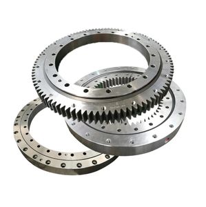
Designing and producing a transmission rate reducer requires an organized technique to ensure optimal efficiency, durability, and performance. This procedure entails understanding application demands, choosing proper elements, doing accurate computations, and adhering to making finest methods. Below is a step-by-step overview to producing a functional transmission rate reducer.
(how to make a gearbox speed reducer gearbox)
** 1. Specify Application Demands **.
Begin by recognizing the functional specifications. Establish input rate (e.g., electric motor RPM), needed result rate, torque ability, power transmission, and ecological problems (temperature level, tons cycles, contaminants). These criteria determine gear ratio, material option, lubrication type, and housing design.
** 2. Select Equipment Kind and Plan **.
Gear reducers frequently utilize spur, helical, bevel, or worm gears. Spur gears are economical for low-speed applications but generate sound. Helical gears use smoother procedure and greater load capability as a result of tilted teeth. Worm gears offer high reduction ratios in compact styles yet have lower effectiveness. Worldly equipment systems are ideal for high torque and space-constrained applications. Choose a setup (parallel shaft, right-angle, coaxial) based upon spatial and efficiency needs.
** 3. Compute Equipment Ratios and Tooth Geometry **.
The equipment proportion (input speed/output rate) determines torque reproduction. For multi-stage reduction, divide the overall proportion right into stages to balance dimension and efficiency. Usage American Equipment Manufacturers Organization (AGMA) standards to determine tooth geometry, making certain appropriate flexing and call tension resistance. Variables include module/pitch, pressure angle (usually 20 °), face width, and account change. Software application tools like AGMA 2001 or ISO 6336 help in verifying tooth toughness and wear limits.
** 4. Material Option and Warmth Therapy **.
Gears are typically made from steel alloys (e.g., AISI 4140, 4340) for high strength and fatigue resistance. Case-hardening processes like carburizing or nitriding enhance surface firmness while keeping a tough core. Softer products like bronze are used for worm wheels to lower rubbing. Think about coverings (e.g., black oxide, zinc) for rust resistance in extreme atmospheres.
** 5. Shaft and Bearing Design **.
Shafts need to stand up to torsional and bending tons without extreme deflection. Calculate minimum shaft size utilizing ASME design codes, factoring in incorporated shock, tiredness, and torque lots. Select bearings (ball, roller, tapered) based on tons capacity and rate. Preload bearings to lessen axial play and make certain placement. Incorporate securing remedies (lip seals, labyrinth seals) to keep lubricating substance and leave out pollutants.
** 6. Housing Layout and Lubrication **.
The real estate encloses parts and maintains placement. Use cast iron or aluminum for strength and resonance damping. Consist of machined pads for mounting and cooling down fins for thermal monitoring. Lubrication reduces rubbing and wear: oil bathrooms fit modest speeds, while forced blood circulation or oil is utilized for high-speed or upright installations. Choose lubes (mineral oil, synthetic PAO) based upon viscosity, temperature variety, and additive packages (anti-wear, EP).
** 7. Production and Setting up **.
Equipment gears using hobbing, shaping, or grinding to attain precise tooth accounts. Harden equipments after cutting to stop distortion. Assemble components step-by-step: press-fit equipments onto shafts, install bearings, and secure shafts within the real estate. Usage shims or flexible end caps to regulate equipment meshing backlash (generally 0.05– 0.1 mm for helical equipments). Do confrontation screening to confirm positioning and surface finish.
** 8. Checking and Quality Assurance **.
Conduct no-load tests to examine noise and resonance. Progressively use torque to validate thermal performance and performance. Action temperature rise, guaranteeing it remains within secure restrictions (e.g., 80 ° C max). Usage vibration analysis to discover misalignment or irregular tooth call. Do devastating screening on models to validate fatigue life and overload capability.
** 9. Maintenance Considerations **.
Design for serviceability: include inspection ports, drain plugs, and grease installations. Suggest periodic oil evaluation to monitor contamination and put on fragments. Define relubrication periods based on operating hours and environmental exposure.
(how to make a gearbox speed reducer gearbox)
Finally, a well-engineered speed reducer equilibriums style rigor, product scientific research, and precision manufacturing. By carefully dealing with each stage– from need evaluation to recognition– designers can supply gearboxes that meet efficiency targets while guaranteeing longevity under requiring problems.


